The Alaska Longline Fishermen’s Association (ALFA), Kempy Energetics, the National Renewable Energy Laboratory and Sandia National Laboratory teamed up through the Energy Transitions Initiative Project Partnership to accelerate an energy transition in the Alaska fishing fleet. We’re working toward hybrid propulsion systems and zero carbon emission propulsion systems. One step in that direction is converting deck hydraulics to electrical systems. Electric troll gurdies have the potential to reduce energy consumed in troll fisheries and lower maintenance requirements. We’re building an electric gurdy to put that idea to the test this summer!
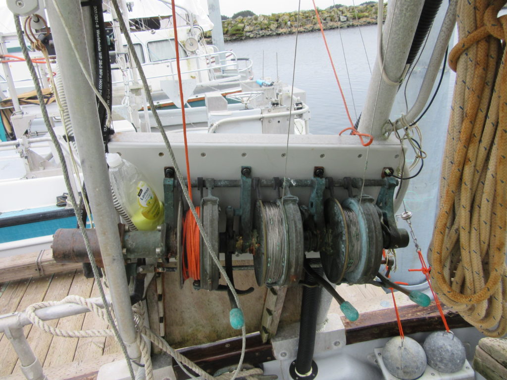
Trolling is a fishing method that consists of cruising through the water at two or three knots while pulling hooks behind the boat. Troll gurdies are the spools used to haul the hooks in and out of the water (see Figure 1). In Alaska, troll gurdies are used in chum, coho, and king salmon fisheries. Each wire has 10 to 20 hooks connected to it while fishing, and the wire is weighted with a 50-70 pound lead ball clipped to its end. Depending on the fishery, a stiff reflector can be clipped to every hook increasing the drag on the wire. Finally, one of the wires will have a Styrofoam float attached to it that allows the hooks to be deployed farther behind the boat. The gurdies pull the wires in and out so that fishermen can harvest fish on the hooks.

Figure 1 Troll gurdies installed on a commercial fishing vessel.
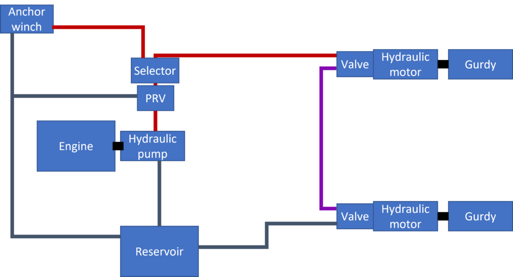
In most vessels, power for the gurdies comes from a hydraulic system. The hydraulic pump is driven by the propulsion engine, either through a gearbox, a direct power takeoff or a belt drive system. The hydraulic pumps are either positive displacement (the amount of oil pumped per revolution is constant) or load sensing (the flow is managed based on the pressure difference across a control valve). Load sensing systems actively control the flow so that the pump delivers the same amount of flow independent of the engine speed. While load sensing systems can be more efficient than positive displacement pumps, positive displacement pumps are more common. Figure 2 illustrates a typical hydraulic system found on a troll vessel.

Figure 2 A common hydraulic system found on troll vessels. Red lines indicate high pressure hoses, blue lines indicate low pressure hoses. The gurdies are plumbed in series, so the connecting hose is at an intermediate pressure. The anchor winch may have an independent pressure relief valve (PRV) built into it.
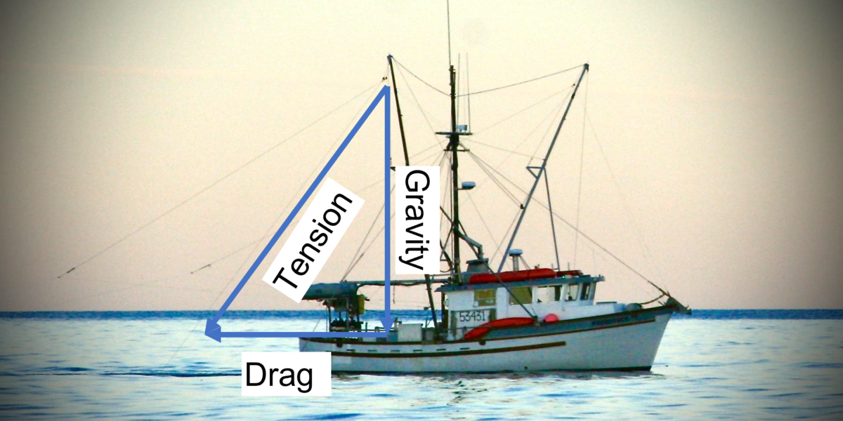
The load that the gurdy motor must haul is equal to the vector sum of the lead weight (minus its buoyancy), the drag of the line and its attachments, and pull from the fish. The weight of the fish is negligible since the fish are approximately neutrally buoyant. Fish may add additional drag to the line, actively pull back on the line, or (if they swim toward the vessel to unweight the hook) have no effect on drag. The total force on the wire can be estimated based on the downward force (approximately equal to the weight of the lead) and the angle of the wire with no float. Figure 3 shows a free body diagram superimposed on an image of a troll vessel actively fishing. The heavy wire is typically less than 45 degrees from vertical while fishing, implying a tension of less than 100 lbs. The hauling speed of the line is variable: fishermen haul the line slowly while removing hooks from the line, but quickly to reach the first hook. The maximum hauling speed is approximately 0.5 fathoms/second (1 m/s). The total mechanical power delivered by the gurdy under normal operation is:

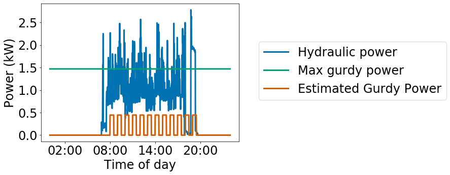
The engine power consumed by a positive displacement pump is the product of hydraulic fluid pressure, pump displacement, and pump rate of rotation. In most vessels this load ranges from 1 to 3 kW, depending on the efficiency of the hydraulic system. The difference between mechanical work delivered by the gurdies and power consumed by the hydraulic system motivates interest in electric gurdy systems for hybrid propulsion systems to reduce battery capacity required to power a day of trolling.

Figure 3 Troller in action with free body diagram for heavy wire.

Figure 4 Measured hydraulic power to supply gurdies on an example troll vessel and estimated gurdy power.
Electric motors to power gurdies must be specified in terms of torque and rate of rotation. The radius of the gurdy spool depends on the amount of wire on the spool. A full spool has a radius of approximately four inches. With 100 lbs of tension, the maximum radius causes a torque of 33 foot-pounds. The rate of rotation to achieve 1 m/s pulling speed is 1.6 Hz.
In some cases, the troll wire might hook a large object that must be hauled in to disentangle from the hooks. This scenario requires much more than the typical torque. The amount of torque that existing gurdy systems can deliver is limited by the gurdy clutch. The torque at which the clutch begins to slip can be adjusted. In one example vessel, the clutch was set to slip at 110 foot-pounds of torque. In order to allow for higher use cases, the motor should be able to supply a maximum torque of 150 foot-pounds. The green line in Figure 4 indicates the mechanical power that would be delivered if the line was hauled continuously at 1.6 Hz and 110 foot pounds of torque. The orange line indicates the estimated mechanical gurdy load throughout the day. In practice, the gurdies are used intermittently but the hydraulics run continuously on this vessel.
Working with a an ALFA fisherman and marine electrician, Kempy Energetics is retrofitting a hydraulic troll gurdy with an electric motor drive according to the specifications defined in the table below. Kempy Energetics bench tested the system this week and it will be headed to the ocean soon to find out how well the motor and connections endure conditions at sea.
| Specification | Value |
| Typical operating torque | 33 foot-pounds |
| Typical operating speed | 1.6 Hz |
| Maximum torque | 150 foot-pounds |
| Maximum operating speed | 2 Hz |
| Voltage | 48 |
| Max current | 50 Amps |

Figure 5 Bench testing the electric gurdy drive

